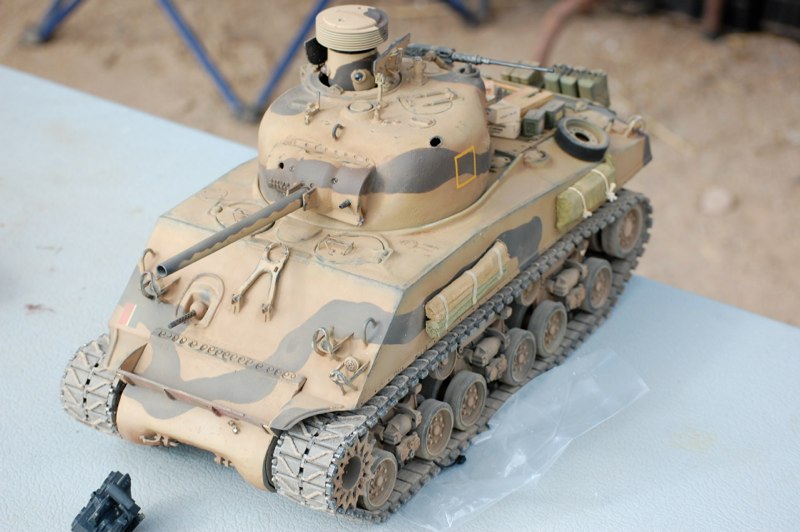
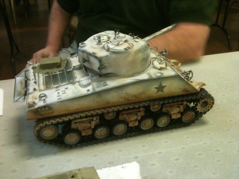
M4A3(W) 75 <ACCURIZED>

CRAIG PIERCE HAS CROSSED THE LINES INTO ALLIED TERRITORY. COMBINING TAMIYA’S KIT WITH A HEFTY AMOUNT OF SCRATCH-BUILDING AND CUSTOM PARTS HIS 75MM SHERMAN IN THE PILOT VEHICLE OF OUR CLUBS “BASTOGNE” GROUP BUILD.

BATTLE OF THE BULGE Sherman

DSC_0561.JPG
DSC_0561.JPG
DSC_0574.JPG
DSC_0574.JPG
DSC_0718.JPG
DSC_0718.JPG
Stock Tamiya turret, Nick Aquilar Mantlet, 75mm gun, split hatch cupola, Schumo brush guards, oil reservoirs, styrene back plate, and suspension upgrades.
Split Hatches added.
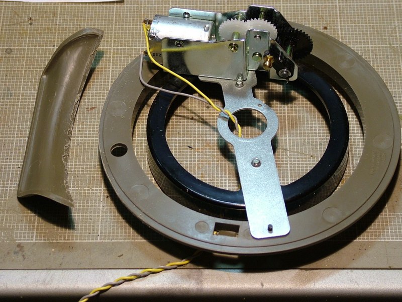
Plan is to make the cupola capable of spinning.
Craig began fitting the Cupola.  Second ventilator removed from turret as it was present on 105 turrets only.
Craig began fitting the Cupola. Second ventilator removed from turret as it was present on 105 turrets only.
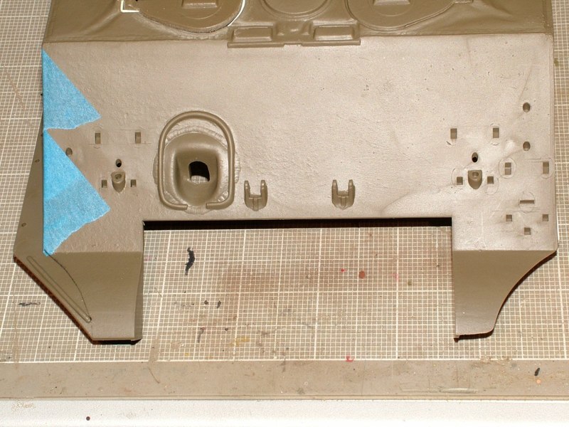
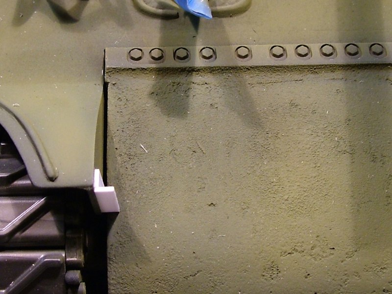
Using a razor saw, motor tool, and files I removed the molded on mud guards off of each side of the upper hull. Then using .020 styrene I fabricated the attachment bars along the bottom edges of the upper hull. The pictures below show the before and after shots of that modification
Then using .020 styrene I fabricated the attachment bars along the bottom edges of the upper hull. Craig “modified” the design to a bit based on some reference material he found.
Using a razor saw, motor tool, and files I removed the molded on mud guards off of each side of the upper hull. Then using .020 styrene I fabricated the attachment bars along the bottom edges of the upper hull. The pictures below show the before and after shots of that modification

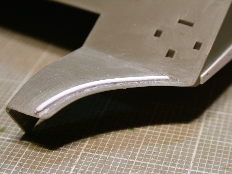
I took these pictures to show the reshaped and thinned front left fender, and the unmodified right kit fender for comparison.
Using a razor saw, motor tool, and files I removed the molded on mud guards off of each side of the upper hull. Then using .020 styrene I fabricated the attachment bars along the bottom edges of the upper hull. The pictures below show the before and after shots of that modification I took these pictures to show the reshaped and thinned front left fender, and the unmodified right kit fender for comparison.
By removing the mud guards the inaccurate shape of the front fenders becomes even more apparent, so I attacked them next. I considered completely removing them and replacing them with new scratch built styrene ones, but thought if I modified the molded kit parts I would hopefully end up with a stronger fender. Once the fender was reshaped, I thinned it from the underside using a motor tool, to create a more realistic scale thickness. Thinning the plastic should help in the weathering process later, where the front fenders will get some dings, dents, and possibly holes added.
I will ultimately graft a replacement stiffening rib to the fender as it was lost during reshaping.
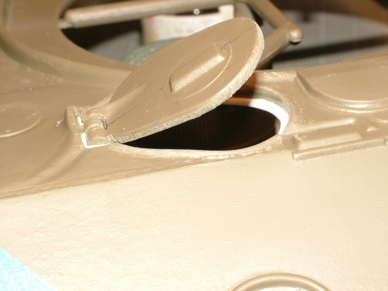
For no reason, other than I can - I usually like to open up hatches and deck lids wherever possible or feasible. DAK co-founder and Sherman fanatic, Ethan, happened to have a left over drivers hatch from a previous build project in which he destroyed the hull but save the molded on hatches. Armed with that little nifty detail I set about cutting and grinding away the drivers hatch.
Reinforcing rib added.
DAK photo
My plan is to put the on/off switch inside the now working driver's hatch.
DAK photo
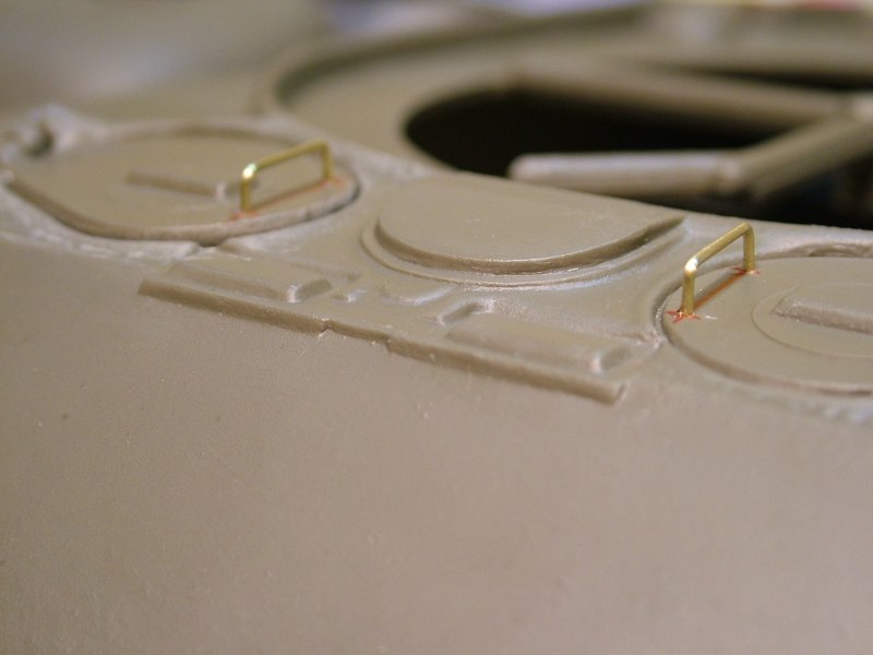
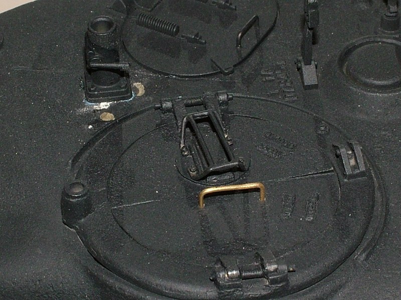
I had some thin gauge brass rod stock, that I thought looked appropriate, so I used that to create the hand grabs on the two front hull hatches. I will generally make grab handles and tie downs and little thin in scale, as I think it helps to offset some of the chunkiness of some of the molded plastic parts.
Once the new hatch was fitted I drilled and pinned the hinge with small brass wire, added an internal lip made from styrene for the hatch to close against, and back filled around the hinge to give it a little resistance. Now the hatch can be posed open at any angle, but still also closes down tight against in internal ring or lip.
Been mostly working on the suspension. Getting it cleaned up, assembled, and dialed in. I used after market metal oil reservoirs on the shock absorbers. The initial plan was to solder them in place but getting the solder to flow was difficult. The pieces being soldered are dissimilar materials, and one is solid while the other is thin walled tubing so getting them to heat evenly for a clean solder joint proved difficult, at least for me. Instead I tacked them in place with CA, and then carefully &quot;spooned&quot; or dribbled 5-minute epoxy down inside the interior of the shock absorber tubing. They seem to be locked in pretty solid now.
Also installed Nick Aguilar's resin cast transmission cover. This piece is truly amazing. After working with urethane resins for years I am all too familiar with how much shrinkage and warpage you can get after you pull parts out of the molds. But this part hugs the lower metal hull like fitted tee on a shapely woman. seriously I don't know if I have ever seen a resin cast piece fit so perfectly to it's intended mating surface. The part looks great and the &quot;cast&quot; texture adds a lot over the stock injection molded plastic.
Also &quot;mocked up&quot; Nicks resin cast mantlet and aluminum turned barrel. It's designed to work in conjunction with the stock 105 mount but you can see gaps behind it. I may have to follow in Ethan's footsteps and use the rotor shield scabbed off of a 1/18th scale 21rst Century Toys 75mm Sherman
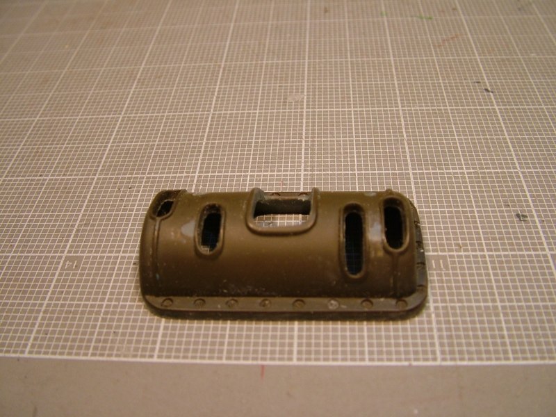
The resin rear deck by Imperial Modelbau is a nice piece and includes cast white metal detail parts and photo-etch deck screens. Should be a pretty straight forward surgery, cutting along some molded in panel lines.
DAK photo
As I mentioned earlier I now have some additonal reference material which has led to me wanting to add some &quot;extras&quot;.

I started with the smoke mortar discharger located on the upper left side of the turret.
As I mentioned earlier I now have some additonal reference material which has led to me wanting to add some &quot;extras&quot;. I started with the smoke mortar discharger located on the upper left side of the turret.
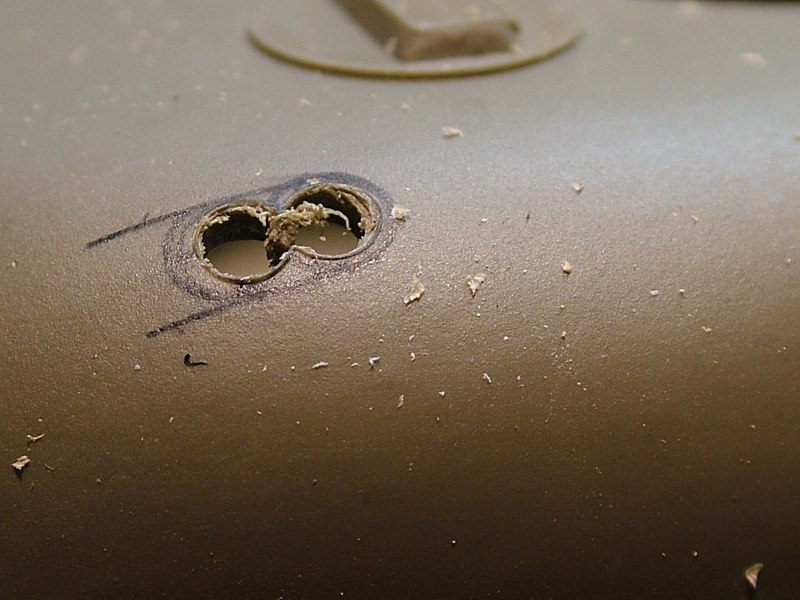
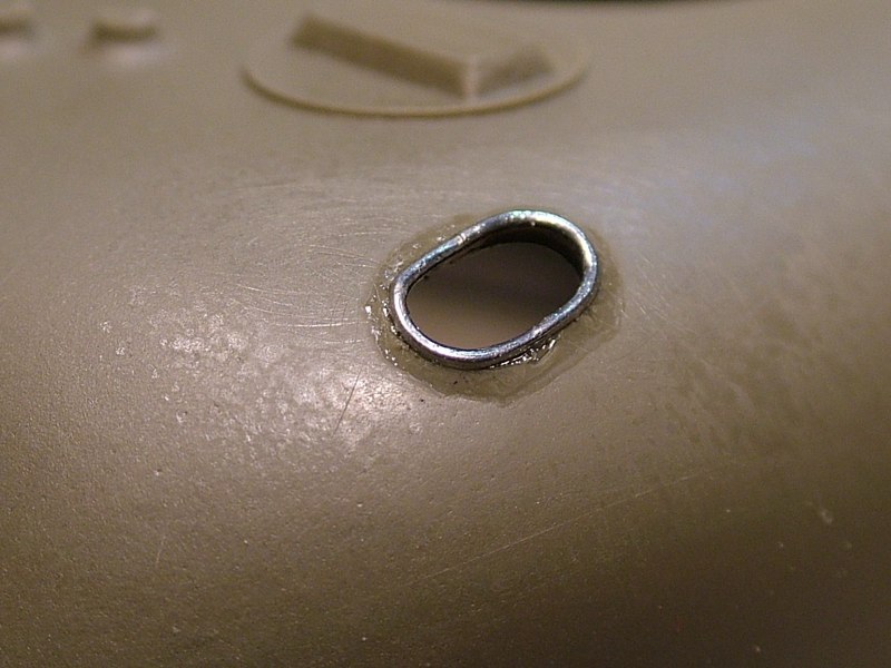
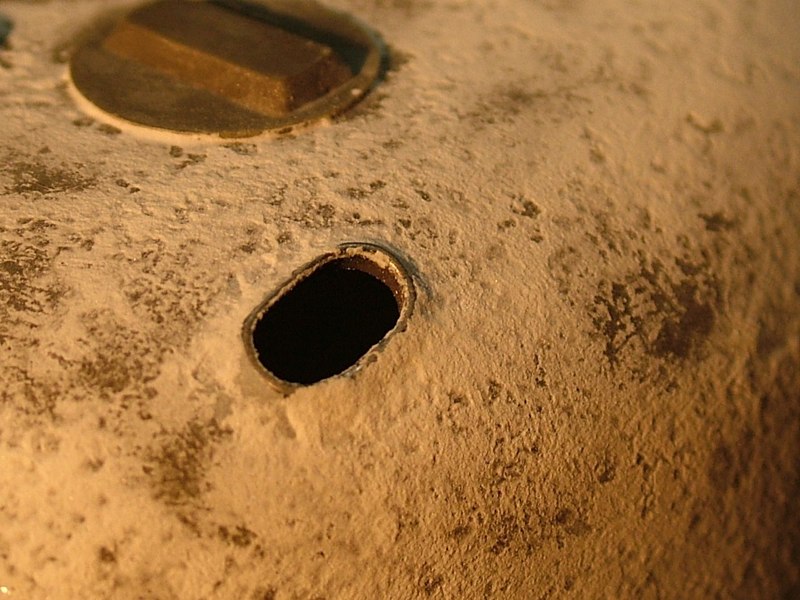
I marked the location using a circle template to draw and mark the center of two adjacent circles. Used a center punch to mark the center and then using a 3/64 drill bit I drilled out both holes. Using a ball end burr in a dremel I thinned the turret plastic directly behind the mortar launcher to give it a more scale appearance.Then I used a fine dremel burr bit and round files to clean up the hole and make it a more symmetrical shape
After I was happy with the overall look and shape of the opening I set about making the raised lip around it. I used thin guage solder bent around a small round file, that had a diameter that was slightly smaller then the opening in the turret.
Using CA I tacked the solder around the inside edge of the opening and blended it into the inside edge of the cut plastic. Then using thick CA I created a fillet around the outside perimeter.
Once the glue was dry I used Tamiya grey putty to blend everyhting together.
I wanted to make working hinges on the low profile gun ring used for TC's cupola, as this is obviously where the TBU will be housed. But I also wanted the ability to close the hatch up while the tank is on display or on the contest table.
So I cut away the molded resin spring in the center section of the hinge pin. Then drilled out both the mount on the ring and the split hatch itself. Using .0315 (1/32nd inch) brass rod I made a new hinge pin. Once that was done I chucked another peice of the same size stock in my Dremel motor tool. I slowly rotated the chuck winding fine (.010) diameter steel thread around the brass rod. Then carefully removed the wound steel thread and slipped it over the brass hinge pin like a sleeve as it passed through the ring and corresponding hatch hinge holes.
It's definitely quicker and easier than doing the entire tank's surface with a small brush and bottle of Mr. Surfacer, I'd guess cheaper as well.
Rustoleum has a line of paints called &quot;Hammered&quot; and it's intended to replicate hand hammered copper or bronze. The only colors they had were mettalics but I thought I would give it a try. 

Using an extra Sherman turret I simply sprayed a few coats of this stuff straight outta the can. Goes on like any other enamel so I started with a few light coats to give it some tooth and ensure good adhesion, then ended with two relatively wet coats and set it aside to dry for a few hours. These pics don't do it justice as the sheen really reflects the light. But I think once you spray a primer gray or matte olive drab finish over it, it should look pretty good.
Rustoleum has a line of paints called &quot;Hammered&quot; and it's intended to replicate hand hammered copper or bronze. The only colors they had were mettalics but I thought I would give it a try. Using an extra Sherman turret I simply sprayed a few coats of this stuff straight outta the can. Goes on like any other enamel so I started with a few light coats to give it some tooth and ensure good adhesion, then ended with two relatively wet coats and set it aside to dry for a few hours. These pics don't do it justice as the sheen really reflects the light. But I think once you spray a primer gray or matte olive drab finish over it, it should look pretty good.
Well you know me, I try to experiment and learn something new on every project, so on this one, one of my goals is to experiment with a new material to create that pitted steel texture.

Well I was at the local Home improvement center and low and behold I found something and I thought, &quot;ya know that may just work, what the hell I'll give it a shot.
Well you know me, I try to experiment and learn something new on every project, so on this one, one of my goals is to experiment with a new material to create that pitted steel texture. Well I was at the local Home improvement center and low and behold I found something and I thought, &quot;ya know that may just work, what the hell I'll give it a shot.
I wanted to block off the rear intakes (grousers) as this was sometimes done on the M4A3.
I started by removing the molded intake covers using a micro-saw. Then using a burr bit in the Dremel tool and files I leveled everything off, leaving the molded on base plate of the intake.
Using a peice of .188 styrene I filled the through hole in the hull.
Filled in the hole.
Filled in the hole.
Then using .020 styrene sheet I made a new base plate &quot;cover&quot;. I added a small washer and hex head attachment bolt both made from Styrene
I added a small washer and hex head attachment bolt both made from Styrene
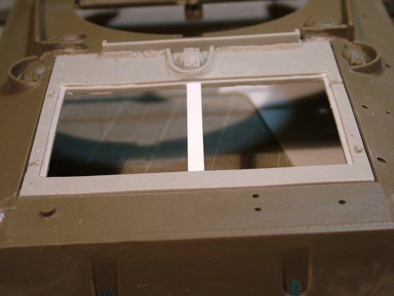
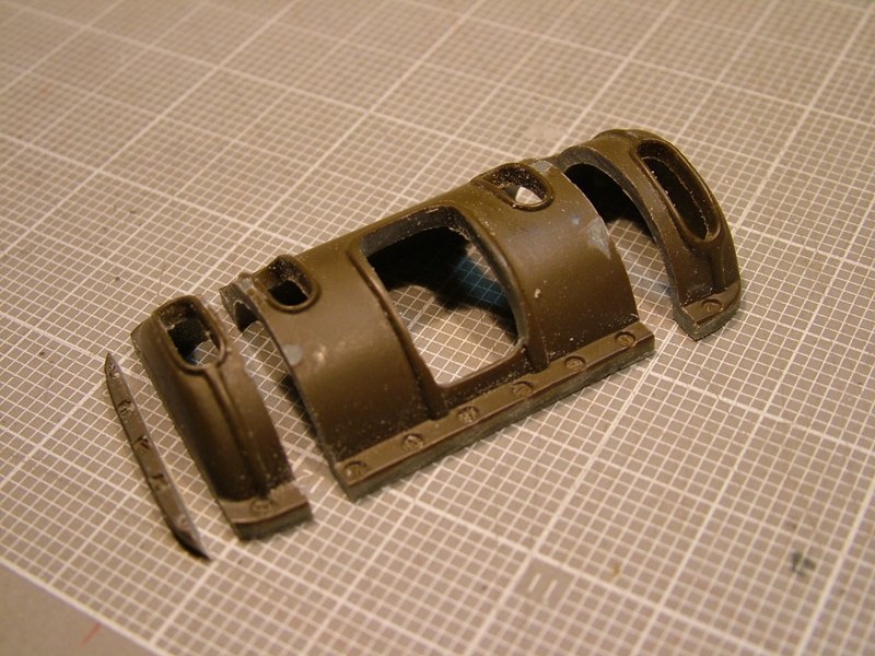
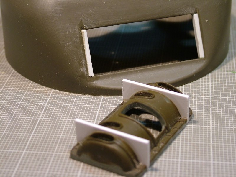
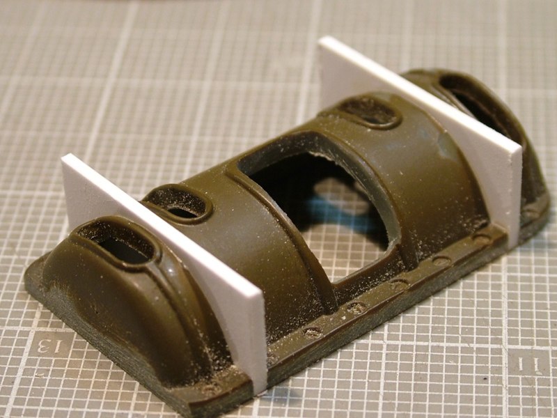
One more piece of the &quot;major&quot; cosmetic surgery now complete. I cut out the solid molded plastic rear deck in preperation for the new Imperial Modelbau resin peice. I started with a reinforced cut-off wheel in my dremel, and slowly worked up to the inside edge of the panel line using finer burr bits, files and sanding sticks. I took a lot of time to finesse the opening as I wanted to ensure a consistent panel line around the new piece. Dry-fitting often, showed some problems with the cast part - it was warped and not quite square.
I made sure my opening was square and true, then used CA to tack the resin piece along to front edge of the back deck closest to the turret. Then I  slightly &quot;tweaked&quot; the resin part to compensate for the warpage. I got the panel line even all the way around the perimeter and tacked it into place. Then using .060 styrene strip on the underneath side I reinforced the glue joints and filled the gap between the plastic hull and resin grill panel effectively creating the bottom of the panel line around the part's perimeter.
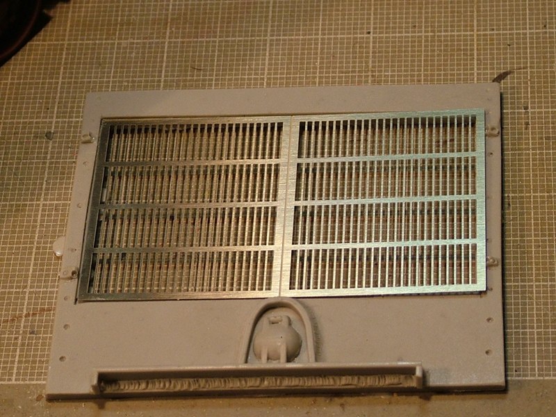
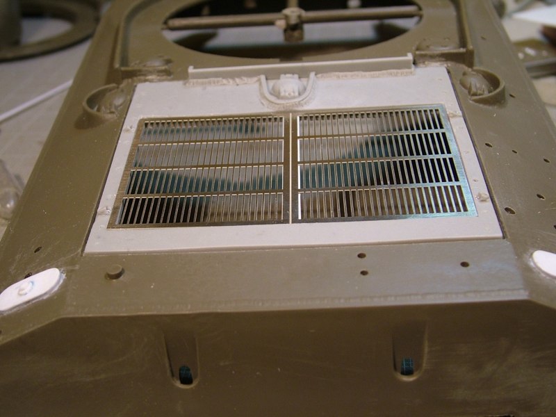
Because the resin part needed some tweaking so did the PE grill that fits into it's recessed opening. Scraping and file work on the the resin lip, plus lots of dry fitting and the grill dropped into place. Then just to add support I also made a brace down the center of the opening to help support the PE grill from being bent inward.
In and done
In and done
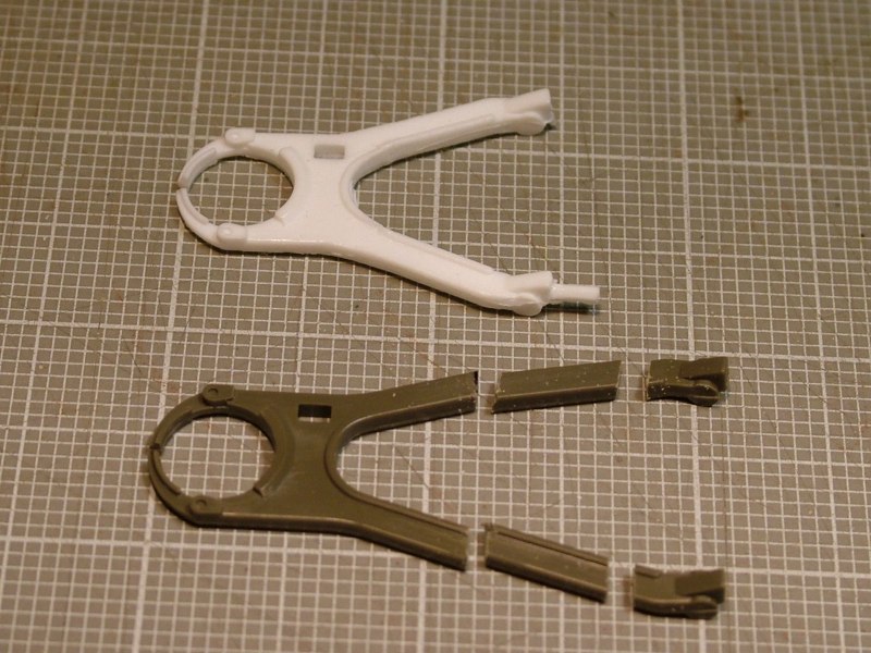
I started by cutting a section of plastic out of each leg. By removing the center section I could still maintain the cross sectional detail of the legs.
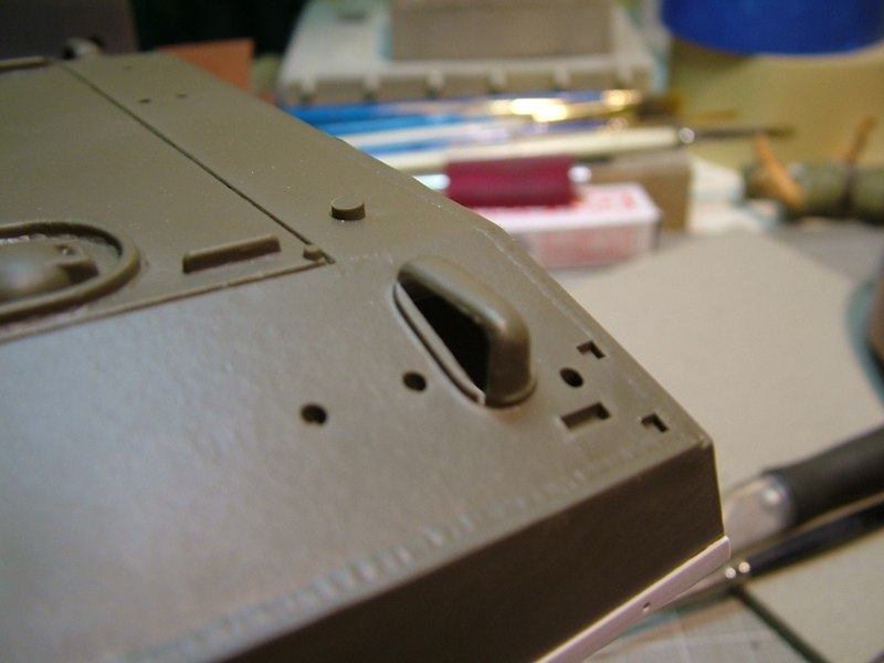
Today I headed back up to the front of the beast and worked on the travel lock. The stock Tamiya 105 travel lock is too large so it needs to be shortened and relocated higher in the front glacis.

Armed with a correct size resin part from Nick Aguilar (it belongs to Ethan) as reference I wanted to see if I could modify the kit part to work.
Today I headed back up to the front of the beast and worked on the travel lock. The stock Tamiya 105 travel lock is too large so it needs to be shortened and relocated higher in the front glacis. Armed with a correct size resin part from Nick Aguilar (it belongs to Ethan) as reference I wanted to see if I could modify the kit part to work.
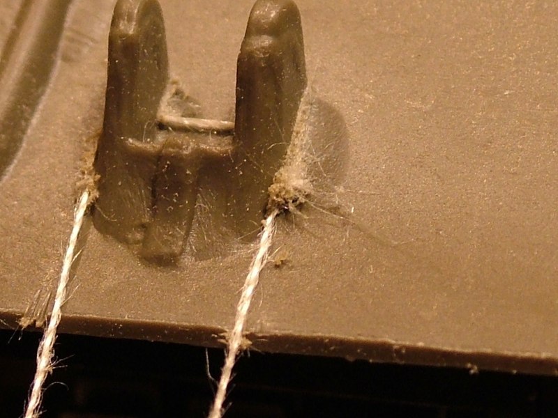
Then using fine cotton thread I sliced the mounting points off of the front glacis. Using the thread means you lose very little material and you can cut irregular shapes and hard to reach places.
I created an new back plate out of styrene and then attached them higher up on the hull.
Now completed, it sits where a M4A3 style travel lock would.
I pinned the assembly to allow the accurate range of motion.
Once the mounting points were dry, I added welds made from Tamiya grey putty, then drilled and pinned the travel lock using .032 brass rod, so it's moveable.
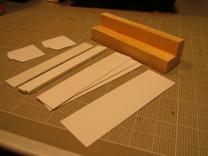
I stood the resin part on end and traced the silouette of each end onto some .040 styrene. Then using three pieces of 1/2&quot; x 1/2&quot; pine cut to length, I glued them in an &quot;L&quot; shape.
I decided to make the airbox out of solid wood covered in a styrene skin. I chose the wood as I wanted to make it stout. I plan on screwing it directly to the rear plate at final assembly.
I stood the resin part on end and traced the silouette of each end onto some .040 styrene. Then using three pieces of 1/2&quot; x 1/2&quot; pine cut to length, I glued them in an &quot;L&quot; shape. I decided to make the airbox out of solid wood covered in a styrene skin. I chose the wood as I wanted to make it stout. I plan on screwing it directly to the rear plate at final assembly.
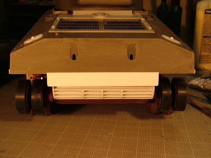
I then went about cutting the styrene louvers and spacers that would be needed
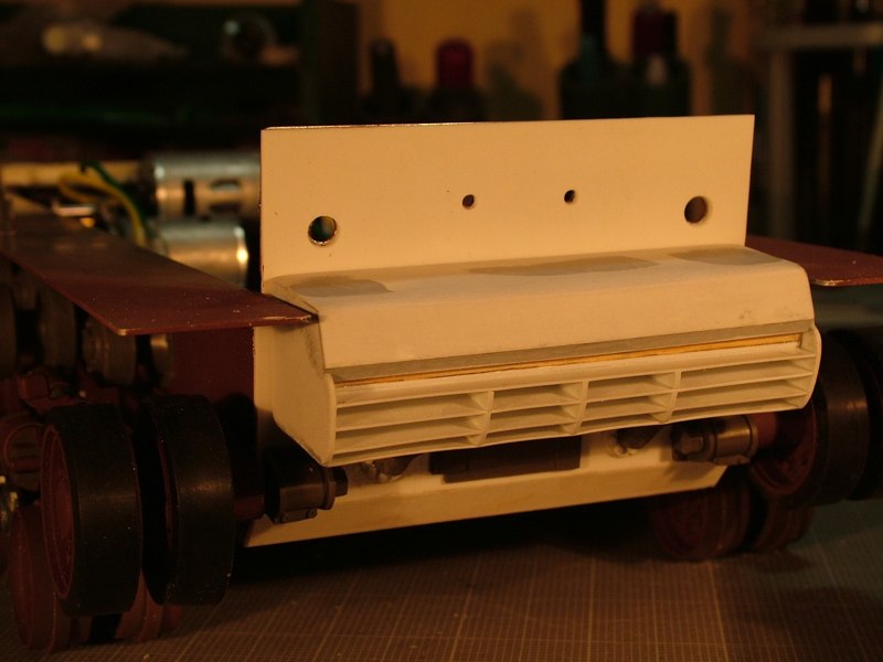
Tonight I decided I was going to tackle the one part I was kind of dreading, the airbox-exhaust deflector. I've been putting this off for awhile, and I just got to a point where I needed to get after it. Ethan had a resin airbox (not sure if it's a BYA or possibly a Nick A. part ) that I used as a pattern, and after much thought of how I wanted to put it together, I threw caution to the wind and started cutting and gluing.
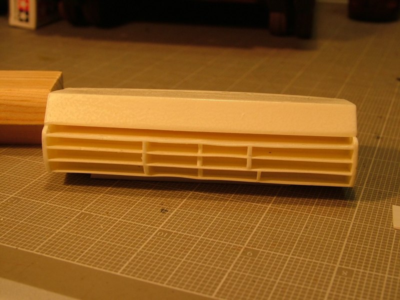
Once I had all the parts sized, cut out, and dry fit several times I got down to construction.

I started by gluing on a .125 x.125 spacer to the bottom edge of the wooden &quot;L&quot;. Then added a .040 louver, then a spacer, another louver, etc. until I had all the louvers in place. I then glued on one end cap to stabilize the louvers and then sanded the other ends flush with the wood. I then added the other end cap and the floor of the airbox.
Once I had all the parts sized, cut out, and dry fit several times I got down to construction. I started by gluing on a .125 x.125 spacer to the bottom edge of the wooden &quot;L&quot;. Then added a .040 louver, then a spacer, another louver, etc. until I had all the louvers in place. I then glued on one end cap to stabilize the louvers and then sanded the other ends flush with the wood. I then added the other end cap and the floor of the airbox.
Anywhere the plastic was attached to the wood I used super glue (CA) and all styrene to styrene joints were put together with solvent (Tenax 7). I hoped in this way the joints would be strong and stable.
Once the lower portion of the box was done, I used .020 styrene to skin the front and top section of the box. Finally I went back and added .125 verticle stiffening ribs to the louvers.
DAK photo
DAK photo
Here are a few shots with the new airbox mocked up on the rear of the tank.
DAK photo
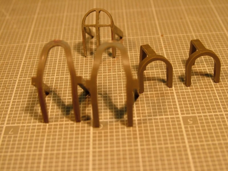
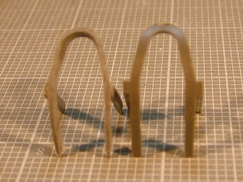
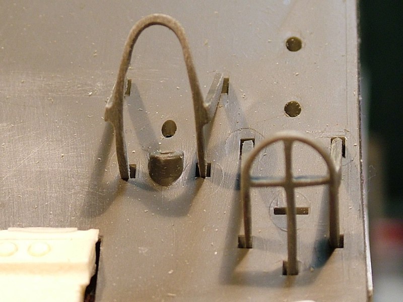
Anyhoo, tonight I decided it was time to see if I could successfully thin all of the stock plastic kit brush guards for the headlights, taillights and horn. Schumo does make a set, but as I've mentioned before I'm cheap and if I can save $70, plus avoid having to wait two-four weeks to get it, I'm at least willing to try. I know my plastic bits will be fragile when they're done, but until I break them beyond repair, who knows maybe then $70 bucks would become a bargain.
Using my calipers I scribed a line at .030 in from the inside edge of each of the guards, effectively marking the center of the .060 thick part. Then using a small burr bit in my dremel I slowly ground away material from the inside perimeter of the part. Then I finished everything off with files and several grits of sandpaper.
They're a definite improvement over the thicker stock parts, and should look more scale once everything is painted up and weathered.
Like I mentioned earlier sorry for the blurry images, but I'm hoping you can still see the results of thinning them down compared to the locator holes in the hull. The first picture shows the stock part on the right and the thinned kit part on the left. My plan is to use solvent to attach them, then reinforce the joint with CA, and finally add a weld bead made of putty.
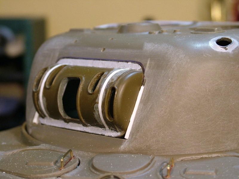
Armed with all the reference material Ethan supplied has really pushed me to add some additonal mods and details. In an earlier post, I mocked up Nick's resin mantlet and aluminum turned barrel. The resin mantlet was desinged to worked with the stock Tamiya 105mm articulation and turret opening, but it does leave some visible and unsightly gaps all the way around the mantlet.
On several earlier Sherman builds, Ethan had robbed the rotor shield off of a 1/18th scale 21rst Century Toy's Sherman, and scabbed it onto the Tamiya turret with good success. Armed with &quot;Modeling the US Army M4 (75mm) Sherman Medium Tank&quot; by Steven Zaloga (Osprey Publishing) I thought I would to tackle the necessary modifications to make my M4A3 as accurate as I reasonably could. Fortunate for me Ethan had an extra 1/18th scale rotor shield he was willing to share.The 21rst Century Toys Sherman has the earlier style M34A1 rotor shield with a flange all the way around it's perimeter, but what I needed to model was the later E5721 configuration without the flange. Because of it's smaller scale the part would also need to be &quot;scaled up&quot; to look correct.
Using a razor saw and miter box I removed the flange off of the left end of the rotor shield, and then cut it into three segments. This way I could leave the inboard slots alone but still grow the over all length of the part. Keeping the gun slot in the center, and maintaining the position of the two inboard slots would be critical. The inboard slots align with two cast bolt heads on Nick's resin mantlet. The plan is to drill out the resin bolt heads and replace them with real ones that will pass through the mantlet, through the two inboard slots on the rotor shield and through backing plates that they will be bolted too. This will effectively &quot;pinch&quot; the rotor shield between the backing plate and the resin mantlet, and the slots will allow the anchoring bolts to travel up and down - while elevating and depressing the gun.
I figured out how much I had to &quot;stretch&quot; the rotor shield and decided the best method would be a combination of lengthening the part and reducing the the size of the turret opening. Actually the turret opening would have to get slightly narrower and taller.
Using .060 styrene spacers I glued everything back together using Tenax 7 plastic solvent. I then added .080 ribs to each side of the stock turret opening using Tenax and reinforced the joint from the backside with CA.
Using the Osprey Book as reference I modified the rear door, scratchbuilt collars for the exhaust stacks, and then modified the kit exhaust to more closely depict the accurate shapes on the M4A3. Once everyhting is painted and weathered I think it should do quite nicely!
Then I installed the scratch built airbox using 3/8&quot; steel cutter screws ran directly into the wood body of the airbox. The screws give me some adjustability, keeps the box secure, and will ultimately allow me to remove it should the need ever arise.
With the putty drying on the turret, it was time to head back out to the ass end of the beast.I think I mentioned before, I try building my tanks to be as stout as I can because I drive them very hard in battle. Whenever possible I use solvent on all plastic to plastic joints, and then usually reinforce those with CA.  So I epoxied Schumo's rear plastic plate to the tail end in an effort to create a better platform for gluing on all the plastic detail bits.
Tonight I installed the rotor shield and did the initial engineering on  the &quot;pinch point&quot; attachment system. I've dry fit the mantlet a few times and have started to figure out if I can still utilize the stock elevation unit, and just design a bracket to attach it directly to the aluminum barrel, or if  I'm going to have to come up with a way of installing a servo unit.
I also puttied over all of the flange bolts in preperation for drilling out new ones that are evenly spaced after everything has been resized. I definitley think the effort was well worth it, and I happy with the results thus far.
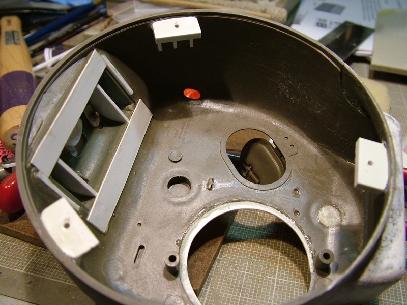
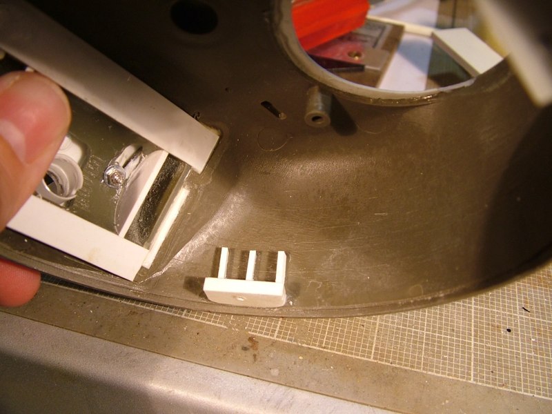
The Sherman turret is a bit tight internally, and once you glue the bottom ring onto the turret it's tough to get at anything inside of there. So taking Ethan's advice and following what he has done on several of his previous builds I modified my turret to make the bottom ring removable.
The bottom ring is made with the bottom portion of the rear bussle molded to it. I simply sliced it off and permanently affixed the bottom of the bussle to the top part of the turret and cleaned up the seam. No worries there really as I will be adding texture to the the turret to make it more accurately depict the sand casting used in the production of it's 1 to 1 counterpart.
As I have mentioned so many times before, my favorite part of this hobby is the finishing (painting and weathering) so I really like to add some of the little extras that make the tank look visually appealing. For this reason I had planned to duplicate the &quot;cast texture&quot; of the turret. Earlier in this thread I had experimented using a &quot;hammered metal&quot; texture paint, but was unhappy with the results. Especially since I used Nick A.&quot;s resin cast transmission cover and that has really nice cast in texture and detail.
I tried something new and am happy with the results. Way back when I had refurbished a Panther G (some of you may have read that thread), and had used vinyl wall spackling to make the zimmermit paste. Because it was a water based material it gave me a lot of control and was very easy to use and add damage too. My plan was to take the same idea one step further using it on this project.
I then fabricated three .060 styrene attachment plates for the inside lip of the turret body, and reinforced them with styrene strip. I drilled corresponding holes through the turret ring and newly made mounting blocks. Then I counter sunk the holes in the bottom of the turret ring, and secured it with flat head screws so they would not interfere with the turret traverse.
A simple and quick fix that solves one of the issues with this kit - Thanks Ethan!
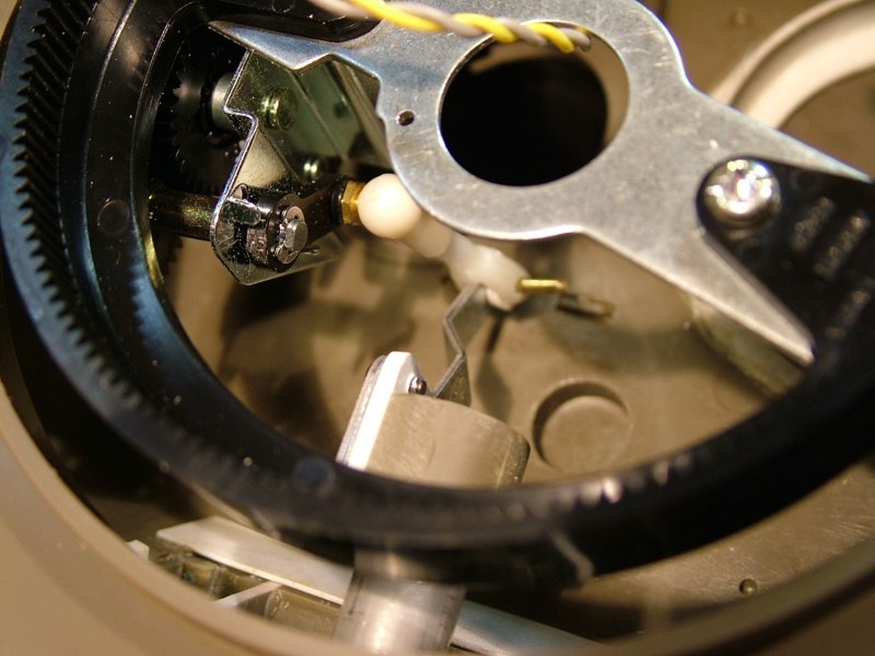
I modified a simple snap link and the ball link provided in the kit, then cut down a piece of all-thread to the appropriate length. In the first few test runs there was bit too much play where the snap link held onto the elevation arm. I rectified this by cutting several .020 spacers out of styrene. Now the modified snap link pivots easily with little to no torquing or twisting.
Working on the elevation I started by using the stock Tamiya elevation arm flipped over. I then used part of the stock emitter clip from the 105 mm Howizter (I'll be putting the emitter in my 75mm aluminum barrel - sans the flash unit) and some flat styrene stock to make a &quot;D&quot; shaped sleeve. I filed a corresponding flat on one side of the aluminum barrel to essentially &quot;key&quot; the barrel and sleeve together.
The best part is that I was able to use the stock elevation unit and and mounting system and not have to mess with locating and aligning a servo. The entire unit is very stable, is still adjustable using the all-thread and it works well, yet it is easily removed and worked on if necessary as the sleeve is nothing more than a friction fit, and all of the linkage can be removed simply by removing the small brass pin.
But I found the spackling was simply too thick and wanted to separate if I tried to thin it too much. So as I returned my can of spackle to my garage, sitting on the same shelf was a bucket of joint compound (wall mud) used for covering tape seams and nail heads when hanging drywall (sheetrock).
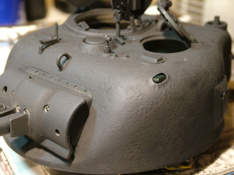
I thinned the joint compound to about the consistency of yogurt and using a triangular make-up sponge I snagged from my girlfriends vanity I set about applying an uneven stipple pattern. As it dried I went back in and added more compound in areas I thought was a bit too smooth. Like the spackle it is water soluble so it is easy to control and clean up. I didn't worry about getting it on molded on details as it easily wiped off with a Q-tip dampened with water.
Once I was happy with the coverage I set the entire turret aside to dry overnight. The next day using a 320 grit sanding sponge I knocked down all the high areas, and made it more uniform. After all was said and done, I added the remaining turret details and locked down the texture coat with several coats of black primer. The layer of joint compound was relatively thin so the primer should penetrate it and effectively lock it down onto the plastic.
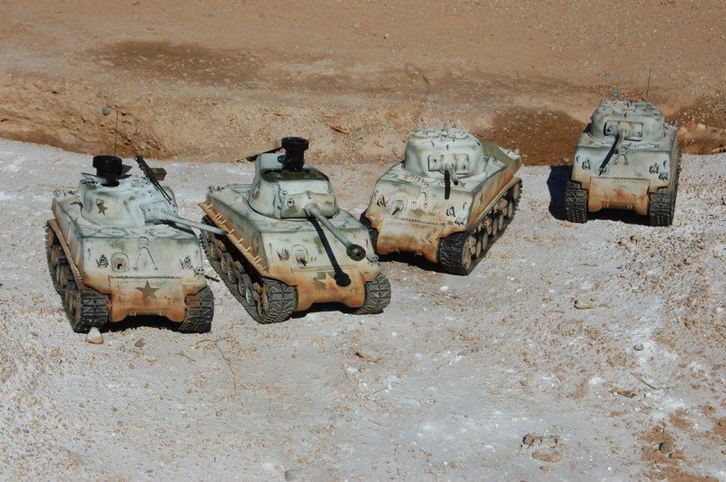
This Sherman will ultimately be white washed and I think the cast texture is really gonna pop once I add some washes to the white color.
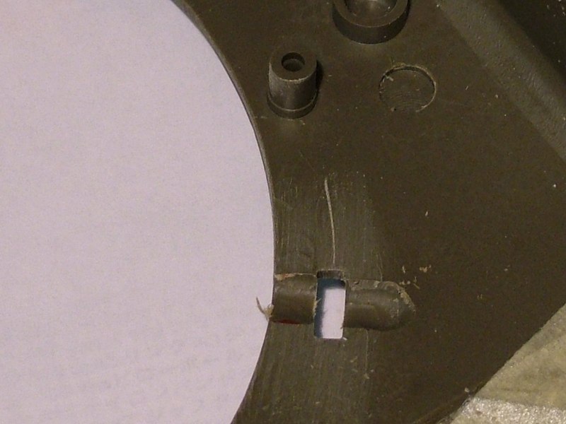
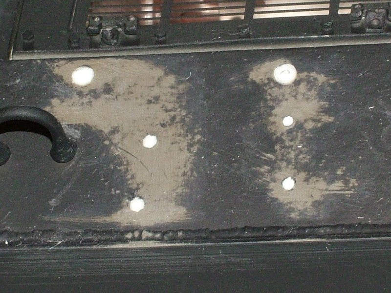
I started by marking three small rectangles on the flat surface of the hull plate below the bottom of the turret ring, and out of the way of all of the traverse mechanism. Then using a 5/64th drill bit I drilled out three holes within each drawn rectangle and then used micro files to join the holes, and square up the edges. I ended up with a rectangular through hole slightly longer and wider than the wheel collet stood on edge.
Moving to the underside of the hull I used a Dremel motor tool to grind a cylindrical channel perpendicular to each rectangular through hole.
Well I took Jeff's idea and applied my poor man approach to solve the same problem. I had purchased and installed wheel bearings when I did the suspension, so I had a baggie containing the stock wheel collets. I also had some styrene tubing of the appropriate diameter.
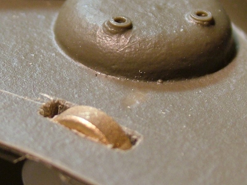
I slowly worked each channel to the proper depth until the wheel collet passed through the lower hull and sat about 1mm higher than the top surface of the lower hull.
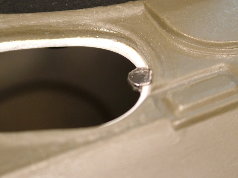
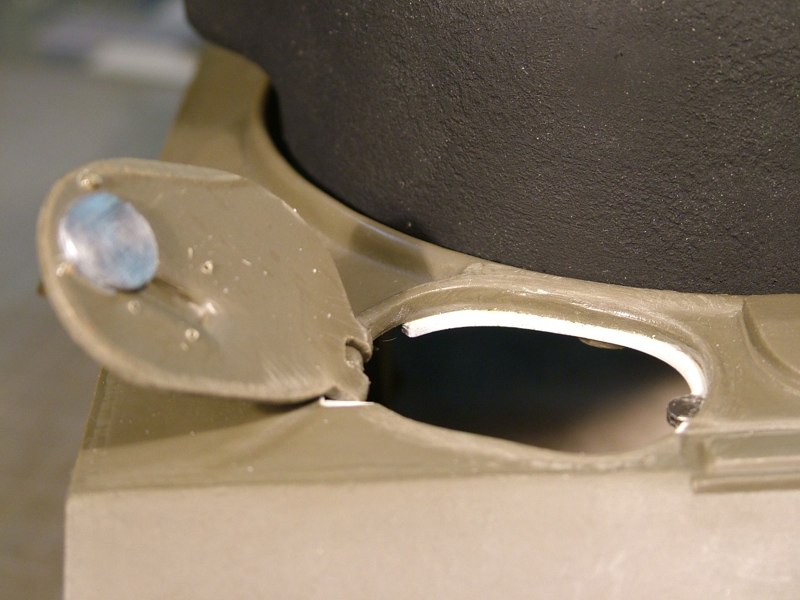
The turret will now sit on top of the three collets that act as a bearing surface. Because they are small they offer little friction or resistance, plus they spin freely, so the wheel collets act as bearings and literally allow the turret to glide over the hull plate
I then cut 1/2&quot; long pieces of the styrene rod to act as an axel that the wheel collet would spin about.
Wired all of the lights and working bow machine gun
Light and horn guards have been added.
Metal brush guards have also been added to both the hull and turret periscopes
Working hatches are now secured with rare earth magnets, and the head of a roofing nail (which provides good surface area)
Working hatches were drilled for new brass grab handles (the stock plastic was simply too weak for the strength of the magnets)
I used the original 1974 kit 30 cal. machine gun to fabricate a coaxial machine gun (cooling holes and barrel have been drilled out)
Handles made of brass wire rplace the plastic handles.
Brass hand grabs, white metal hinges and hex bolt details have been added to the new resin rear deck
I chose to use the stock plastic parts that have been thinned to half their original thickness
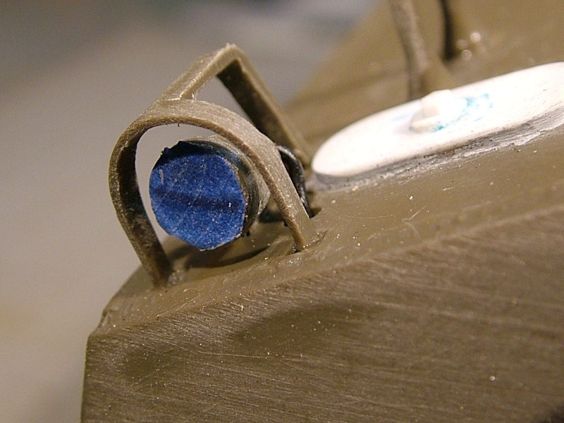
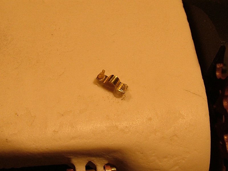
Using some scrap brass strip and a spare wing-nut, I pilfered from the &quot;K&quot; sprue of the Tamiya Tiger I static kit, I added the cable stay to Nick's cast resin transmission cover.
DAK photo
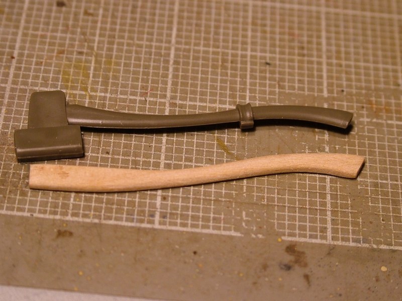
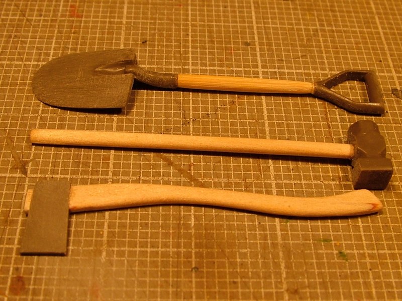
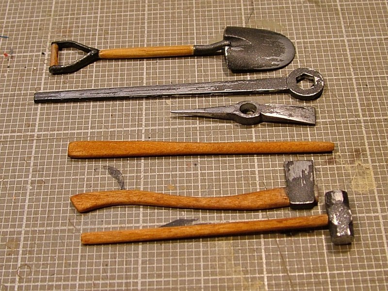
Armed with some Bamboo skewers, popcycle sticks, and round tooth picks I set out to replicate the tools.
It's pretty straight forward really, I just traced the handle shape (in the case of the axe handle) or took some simple dimensions (sledge and shovel) like the diameter and the length
Plus the kit part is molded as one with the tool holder, so I cut it off and filed the axe head to shape.
Then started cutting, and shaping using my Dremel motor tool, files, and sanding blocks.
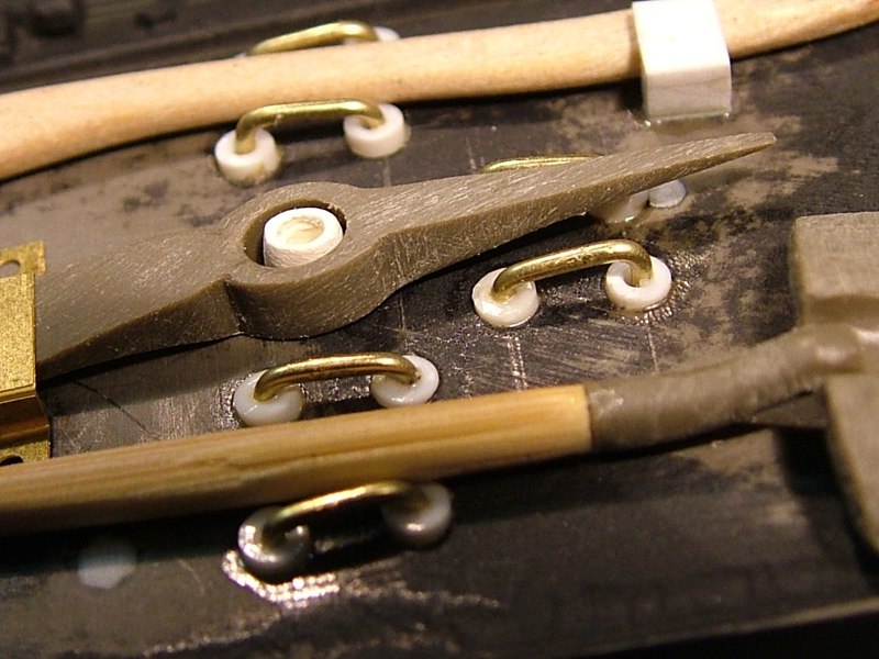
Once the handles were the desired shape and size I reworked all of the plastic parts that needed modifying. The axe head for example, is not molded to show the wooden handle passing through the metal axe head, so I drilled mine out so that the new wooden handle passes through the axe head just like on it's life size counter part.
By removing the thick and chunky plastic tool holder I can replicate it and tie down straps and buckles with photoetch, sheet styrene, and brass or copper wire.
I went to the trouble of scratch building real wood tool handles, but in the process lost the molded on mounting points. I had planned all along to replace them with more accurate PE and styrene fasteners. But I also forgot to &quot;fill in&quot; the attachment holes molded into the upper hull. I used various diameter styrene rod to fill the hole.
The rod was glued with solvent from the inside, cut almost flush with the outer surface, then filed and sanded smooth. New tool fasteners will be next
Plus I had neglected to modify the stock machine gun mount. On the Tamiya kit the machine gun mount for the top of the turret is made with a three legged raised design made to go over the the top of the ventilator. Well if you recall the 75mm doesn't have the extra ventilator, so it was removed (filled and puttied), so obviously the machine gun could now be secured flush to the turret top with a mounting plate. The first picture show the unmodified stock part, and the second picture shows it with the &quot;tri-pod&quot; legs ground off
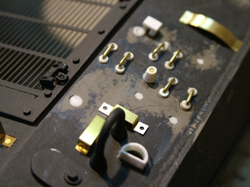
For the functional tool tie downs I marked and drilled .090&quot; through holes in the hull .200 on-center.
Armed with several reference books (one really good one on modeling the 75mm Sherman by Osprey [Steve Zaloga]) I spent the last few evenings working away at all of the scratch built tool holders and fasteners.
All of the tools had already been modified with real wood handles and the stock molded-on tool holders have been removed. This meant reworking most of the tool heads and/or the replicated metal parts of the tools as well.
Using styrene and brass rod, strip, sheet, and tubing I made several types of hangers for each of the tools. Then I went into my spares box and used some extra PE pieces that I either modified or scratch built just using the left over PE fret.
Once the holes were drilled I cut pieces of .090&quot; styrene tubing to short lengths (.060&quot; long) on my chopper. The center hole of the .090&quot; tubing is approximately .030&quot; so I used some 1/32 (.0315&quot;) diameter brass rod bent into a horseshoe shape. The styrene tubing was inserted into the holes and left standing about .030&quot; proud of the outer hull surface.
The tubing was glued on the inside surface of the hull using solvent (MEK). Once the solvented tubing had dried the bent brass rod was inserted into the tubing and glued from the inside using CA
Once the paint is applied all of the tools will be lashed down to the tie downs using straps made from tape with PE buckles.
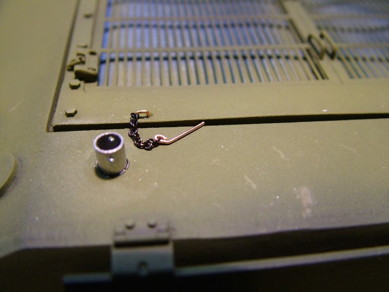
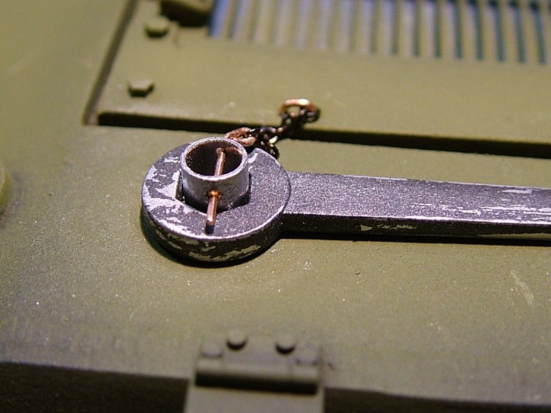
Using .020&quot; diameter copper wire I made the retainer pins that secure the gas caps in place on the rear deck. I used an .024&quot; micro drill to drill a hole in each gas cap and then bent and inserted the copper wire.
I then bent lengths of the same wire around a .060 diameter brass rod to create the retaining &quot;hoop&quot; which would get attached to the rear deck. Using the same drill bit I drilled two small holes and inserted the retainer hoop.
After threading one end of a small length of chain onto the hoop and the other onto the retaining pin everything was secured with CA
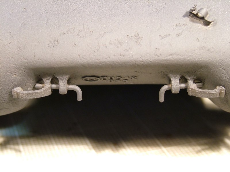
I decided to go back in and add the step and tow pin that are supposed to be on this version.
I used Nick R.'s resin cast transmission cover which features a double eyelet design
Using high quality artist's oil paints I mixed a thin wash that I then used to stain the wooden handles a light mahogany color. I chose to use the oil paints over water colors in hopes that the paint and thinner would not raise the grain as much as water colors would, plus the density of pigments in the oil paint would hopefully produce a richer colored effect. I then set that aside to dry for a couple of days. 
After the paint was dry I sealed the paint and wood with a quick shot of Testor Dullcoat. Then added a wash of dark brown water color to help accentuate the grain strike.
Using high quality artist's oil paints I mixed a thin wash that I then used to stain the wooden handles a light mahogany color. I chose to use the oil paints over water colors in hopes that the paint and thinner would not raise the grain as much as water colors would, plus the density of pigments in the oil paint would hopefully produce a richer colored effect. I then set that aside to dry for a couple of days. After the paint was dry I sealed the paint and wood with a quick shot of Testor Dullcoat. Then added a wash of dark brown water color to help accentuate the grain strike.
The wooden handles were then masked off and the metal parts of the tools were sprayed using Testor's brand buffable metalizer paint. I chose stainless steel and plate aluminum. Once a few light coats were applied I allowed the lacquer based paint to dry thoroughly. Once dry I used a soft cotton rag to buff the finish to a bright sheen. Next will come a layer of darker mettalic grey or gunmetal acrylic paint. Once that is painted on I will be able to &quot;rub through&quot; the acrilic paint exposing the brighter color underneath making it look the metal in worn and shiny on the edges. Then I will add layers of green and whitewash paint to represent field applied paint that will also be worn through.
All of the Shermans in this group build (mine included) were all first finished in flat black primer. This served as a solid foundation color, and tied all of the different medias (plastic, resin, brass, copper, aluminum) together.
The dark color was applied as a pre-shade so it also serves as the first layer of weathering. Meaning that as the color coats are applied I intentionally let the black undercoat show through, especially at the edges and soft corners.
This helps to add a tremendous amount of depth and dimension to the paint. This technique really helps prevent that flat &quot;toylike&quot; appearance, especially on monochromatic schemes.
Remember too, that the olive green (which was intentionally lightened) will also serve only as a base color, as these tanks will ultimately be whitewashed. The hope is that by layering the finish I can more accurately duplicate what was applied to the real 1 to 1 tanks these represent.
As promised here is the next round of in-process pictures showing the progression of the tools. All of the metal parts were painted with a mixture of matte black and gun metal acrylic paint. Once dried the paint was &quot;scuffed off&quot; with a damp Q-tip and rolled up paper towel.
Once I was happy with the wear pattern the tools were given a thin wash of matte black acrylic and then dusted with Tamiya steel weathering paste to help even everything out and give the tools a more consistent metallic sheen
Came to a screeching halt on the painting of the group of Shermans (which includes mine) as I am awaiting delivery of some Archer transfers I need for the bumper codes. And those need to go on next, before I start the whitewashing process. Hopefully I'll get my hands on them tomorrow. But in the meantime I went back to adding some details.
This time I followed Ethan's lead and added a more accurate tool bracket for the ideler adjustment wrench on the back ledge of the rear deck. Tamiya simply molds a raised cylindrical post or boss on the rear hull plate. This can easily be improved.
So I shaved the post off marked the center of the location, then drilled a .156&quot; (5/16 inch)diameter through hole. Then cut a like diameter piece of aluminum tubing and inserted it. I then used an .024&quot; micro drill and drilled a through hole in the top edge of the aluminum tubing to accept a locking pin.
I used a short piece of .020&quot; copper wire to make the retaining pin and attachment hoop. The retaining pin had a small loop added by wrapping the wire around the tip of some fine tweezers. I then threaded some fine chain onto the retaining pin and the attachment hoop. The hoop was then CA'd into two small holes that had been drilled into the surface of the rear deck using the same .024&quot; drill bit chucked in a pin vice.
Finally before I called it a night (it's just after 1am local time) I decided to head back up to the front of the Allied beast. Because this group of Shermans have all had the majority of the same modifications and will wear the same paint scheme I want to make each tank still look individual and unique, so for mine I plan on scratch building some tow cables, and want to add quite a bit of stowage.
I added the commonly seen wooden &quot;shelf&quot; across the front of the transmission cover, and captured between the front fenders. But I designed mine in such a way that I can still add the tow cable without it interfering with the stowage shelf.
I started by making two pieces of 90 degree angle stock out of .125 X .030 styrene strip cut to .400 in length. The strip was glued at right angles using MEK solvent, and then added to the bottom edge of the inside lip of the front fenders.
I then used two pieces of .25 X .080 Balsa strip to make the structural wooden planks. After cutting them to length, I used a small chisel to split and chip the edges giving them that very old used look of discarded lumber (perhaps the crew picked them up in the rubble a bombed out building somewhere in France). I glued the two strips together using wood glue and then added support batons to the underneath side from additional pieces of balsa strip. Once I was happy with the overall size and shape I used a course rasp to add scratches and gouges to stay consistent with the look. They should look pretty cool with chipped and peeled paint.
I then cut out a section of the wood to make a pass through where the tow cable will be attached to it's cable tie down lower down on the transmission cover.
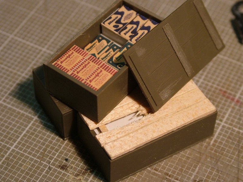
Next came the K ration boxes, as I wanted to add some visual interest I decided to spruce them up a bit as well.
I searched the internet and found decent pictures of individual meal meal boxes (Breakfast, Supper, and Dinner) and they were in very colorful boxes. Armed with these pictures and using the stock Tamiya &quot;wooden&quot; crates my plan was to have one completely sealed crate, one that has a broken lid that you can see the crate's contents through the broken wood slats, and a third crate that has the top completely removed and some of the individual rations boxes removed.
To fill the void of the empty crate (and make them look full) would require an internal structure to affix the reduced meal box pictures too. Using thin styrene sheet I made a simple shelf, for the crate with the broken lid, and for the open crate, that would have some of the meal boxes removed, I made a shelf with a stepped down area in the center. I then added styrene strip to the side walls of the crate that would act as shelf supports
Next I used sheet balsa to make a &quot;new&quot; real wood crate lid. After cutting the new lid to size I simply scored lines into the surface to represent the wooden slats. I then took some small square stock and made batons (Braces) on the underside of the lid. Then using an X-acto blade and 1/4&quot; chisel blade I &quot;broke&quot; several of the slats to make the crate lid look damaged
Obviously the crates themselves still need to be painted as does the white styrene used for the interior structure, decals added and weathering applied. But here are some in-progress pictures to give you an idea what they will look like
DAK photo
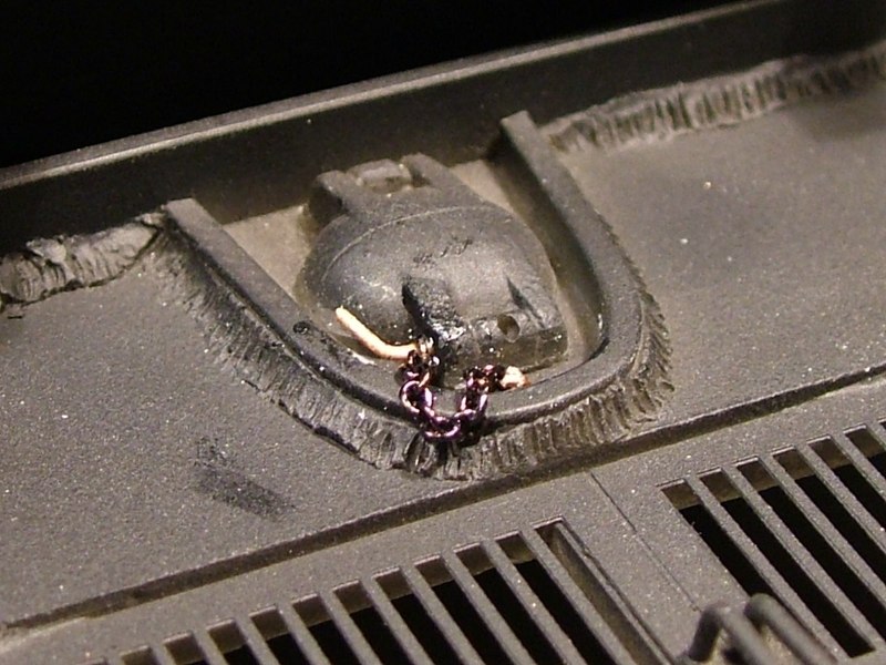
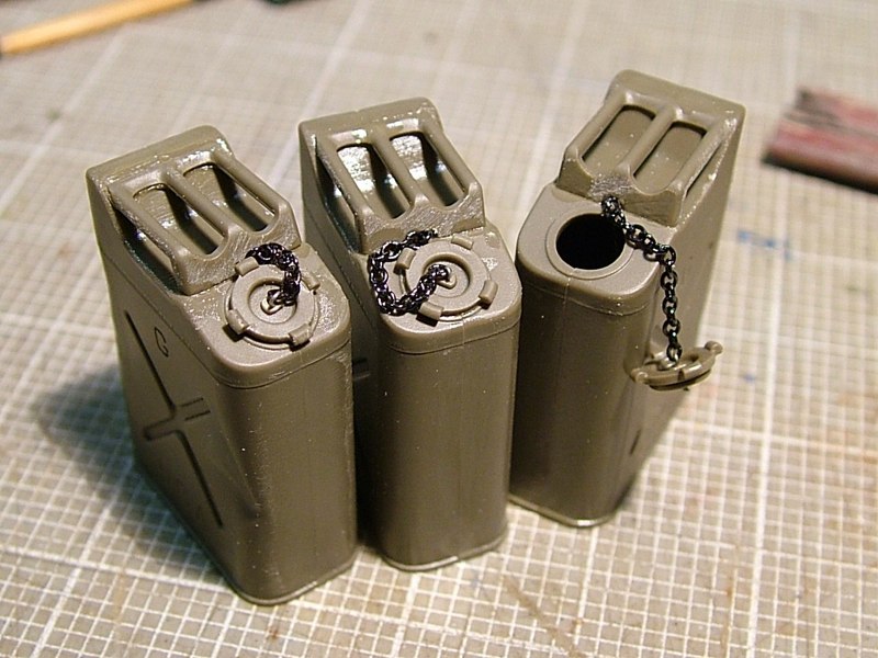
Following Ethan's lead, I added a retaining chain to hold the fuel filler cap on the jerry cans. I drilled out each of the caps for the 5 gallon fuel cans with a .020&quot; micro drill bit in my pin vice. Then I used a small piece of .010&quot; wire to make a retaining hoop to secure a piece model railroad chain through the center of the cap. I then drilled another hole in the center of the fuel can before I glued on the handle, and secured the opposite end of the retaining chain through a second hoop made from the same wire.
IMG_0073.JPG
IMG_0073.JPG
IMG_0076.JPG
IMG_0076.JPG